
Page 187 - Understanding Automotive Electronics
P. 187
2735 | CH 5 Page 174 Tuesday, March 10, 1998 11:10 AM
5 THE BASICS OF ELECTRONIC ENGINE CONTROL
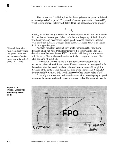
The frequency of oscillation f of this limit-cycle control system is defined
L
as the reciprocal of its period. The period of one complete cycle is denoted T ,
p
which is proportional to transport delay. Thus, the frequency of oscillation is
1
f = ------
L
T p
where f is the frequency of oscillation in hertz (cycles per second). This means
L
that the shorter the transport delay, the higher the frequency of the limit cycle.
The transport delay decreases as engine speed increases; therefore, the limit-
cycle frequency increases as engine speed increases. This is depicted in Figure
5.18 for a typical engine.
Although the air/fuel Another important aspect of limit-cycle operation is the maximum
ratio is constantly swing- deviation of air/fuel ratio from stoichiometry. It is important to keep this
ing up and down, the deviation small because the net TWC conversion efficiency is optimum for
average value of devia- stoichiometry. The maximum deviation typically corresponds to an air/fuel
tion is held within ±0.05 ratio deviation of about ±1.0.
of the 14.7:1 ratio. It is important to realize that the air/fuel ratio oscillates between a
maximum value and a minimum value. There is, however, an average value for
the air/fuel ratio that is intermediate between these extremes. Although the
deviation of the air/fuel ratio during this limit-cycle operation is about ±1.0,
the average air/fuel ratio is held to within ±0.05 of the desired value of 14.7.
Generally, the maximum deviation decreases with increasing engine speed
because of the corresponding decrease in transport delay. The parameters of the
Figure 5.18
Typical Limit-Cycle
Frequency versus
RPM
FPO
174 UNDERSTANDING AUTOMOTIVE ELECTRONICS