
Page 183 - Understanding Automotive Electronics
P. 183
2735 | CH 5 Page 170 Tuesday, March 10, 1998 11:10 AM
5 THE BASICS OF ELECTRONIC ENGINE CONTROL
Closed-Loop Control
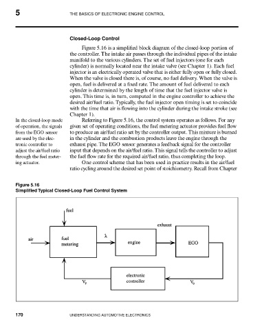
Figure 5.16 is a simplified block diagram of the closed-loop portion of
the controller. The intake air passes through the individual pipes of the intake
manifold to the various cylinders. The set of fuel injectors (one for each
cylinder) is normally located near the intake valve (see Chapter 1). Each fuel
injector is an electrically operated valve that is either fully open or fully closed.
When the valve is closed there is, of course, no fuel delivery. When the valve is
open, fuel is delivered at a fixed rate. The amount of fuel delivered to each
cylinder is determined by the length of time that the fuel injector valve is
open. This time is, in turn, computed in the engine controller to achieve the
desired air/fuel ratio. Typically, the fuel injector open timing is set to coincide
with the time that air is flowing into the cylinder during the intake stroke (see
Chapter 1).
In the closed-loop mode Referring to Figure 5.16, the control system operates as follows. For any
of operation, the signals given set of operating conditions, the fuel metering actuator provides fuel flow
from the EGO sensor to produce an air/fuel ratio set by the controller output. This mixture is burned
are used by the elec- in the cylinder and the combustion products leave the engine through the
tronic controller to exhaust pipe. The EGO sensor generates a feedback signal for the controller
adjust the air/fuel ratio input that depends on the air/fuel ratio. This signal tells the controller to adjust
through the fuel meter- the fuel flow rate for the required air/fuel ratio, thus completing the loop.
ing actuator. One control scheme that has been used in practice results in the air/fuel
ratio cycling around the desired set point of stoichiometry. Recall from Chapter
Figure 5.16
Simplified Typical Closed-Loop Fuel Control System
170 UNDERSTANDING AUTOMOTIVE ELECTRONICS