
Page 181 - Understanding Automotive Electronics
P. 181
2735 | CH 5 Page 168 Tuesday, March 10, 1998 11:10 AM
5 THE BASICS OF ELECTRONIC ENGINE CONTROL
Figure 5.15
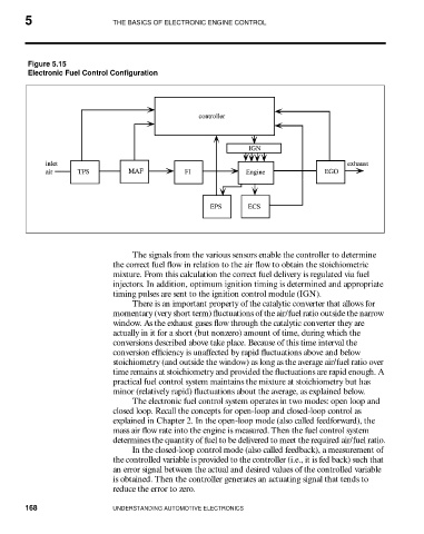
Electronic Fuel Control Configuration
The signals from the various sensors enable the controller to determine
the correct fuel flow in relation to the air flow to obtain the stoichiometric
mixture. From this calculation the correct fuel delivery is regulated via fuel
injectors. In addition, optimum ignition timing is determined and appropriate
timing pulses are sent to the ignition control module (IGN).
There is an important property of the catalytic converter that allows for
momentary (very short term) fluctuations of the air/fuel ratio outside the narrow
window. As the exhaust gases flow through the catalytic converter they are
actually in it for a short (but nonzero) amount of time, during which the
conversions described above take place. Because of this time interval the
conversion efficiency is unaffected by rapid fluctuations above and below
stoichiometry (and outside the window) as long as the average air/fuel ratio over
time remains at stoichiometry and provided the fluctuations are rapid enough. A
practical fuel control system maintains the mixture at stoichiometry but has
minor (relatively rapid) fluctuations about the average, as explained below.
The electronic fuel control system operates in two modes: open loop and
closed loop. Recall the concepts for open-loop and closed-loop control as
explained in Chapter 2. In the open-loop mode (also called feedforward), the
mass air flow rate into the engine is measured. Then the fuel control system
determines the quantity of fuel to be delivered to meet the required air/fuel ratio.
In the closed-loop control mode (also called feedback), a measurement of
the controlled variable is provided to the controller (i.e., it is fed back) such that
an error signal between the actual and desired values of the controlled variable
is obtained. Then the controller generates an actuating signal that tends to
reduce the error to zero.
168 UNDERSTANDING AUTOMOTIVE ELECTRONICS