
Page 180 - Understanding Automotive Electronics
P. 180
2735 | CH 5 Page 167 Tuesday, March 10, 1998 11:10 AM
THE BASICS OF ELECTRONIC ENGINE CONTROL 5
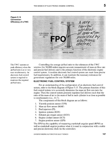
Figure 5.14
Conversion
Efficiency of a TWC
FPO
The TWC operates at Controlling the average air/fuel ratio to the tolerances of the TWC
peak efficiency when the window (for 50,000 miles) requires accurate measurement of mass air flow rate
air/fuel ratio is at or very and precise fuel delivery and is the primary function of the electronic engine
near stoichiometry. An control system. A modern electronic fuel control system can meet these precise
electronic fuel control fuel requirements. In addition, it can maintain the necessary tolerances for
system is required to government regulations for over 50,000 miles.
maintain the required
ELECTRONIC FUEL CONTROL SYSTEM
air/fuel ratio.
For an understanding of the configuration of an electronic fuel control
system, refer to the block diagram of Figure 5.15. The primary function of this
fuel control system is to accurately determine the mass air flow rate into the
engine. Then the control system precisely regulates fuel delivery such that the
ratio of the mass of air to the mass of fuel in each cylinder is as close as possible
to stoichiometry (i.e., 14.7).
The components of this block diagram are as follows:
1. Throttle position sensor (TPS)
2. Mass air flow sensor (MAF)
3. Fuel injectors (FI)
4. Ignition systems (IGN)
5. Exhaust gas oxygen sensor (EGO)
6. Engine coolant sensor (ECS)
7. Engine position sensor (EPS)
The EPS has the capability of measuring crankshaft angular speed (RPM) as
well as crankshaft angular position when it is used in conjunction with a stable
and precise electronic clock (in the controller).
UNDERSTANDING AUTOMOTIVE ELECTRONICS 167