
Page 230 - Understanding Automotive Electronics
P. 230
2735 | CH 6 Page 217 Tuesday, March 10, 1998 1:10 PM
SENSORS AND ACTUATORS 6
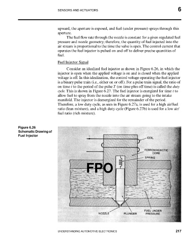
upward, the aperture is exposed, and fuel (under pressure) sprays through this
aperture.
The fuel flow rate through the nozzle is constant for a given regulated fuel
pressure and nozzle geometry; therefore, the quantity of fuel injected into the
air stream is proportional to the time the valve is open. The control current that
operates the fuel injector is pulsed on and off to deliver precise quantities of
fuel.
Fuel Injector Signal
Consider an idealized fuel injector as shown in Figure 6.26, in which the
injector is open when the applied voltage is on and is closed when the applied
voltage is off. In this idealization, the control voltage operating the fuel injector
is a binary pulse train (i.e., either on or off). For a pulse train signal, the ratio of
on time t to the period of the pulse T (on time plus off time) is called the duty
cycle. This is shown in Figure 6.27. The fuel injector is energized for time t to
allow fuel to spray from the nozzle into the air stream going to the intake
manifold. The injector is deenergized for the remainder of the period.
Therefore, a low duty cycle, as seen in Figure 6.27a, is used for a high air/fuel
ratio (lean mixture), and a high duty cycle (Figure 6.27b) is used for a low air/
fuel ratio (rich mixture).
Figure 6.26
Schematic Drawing of
Fuel Injector
FPO
UNDERSTANDING AUTOMOTIVE ELECTRONICS 217