
Page 233 - Understanding Automotive Electronics
P. 233
2735 | CH 6 Page 220 Tuesday, March 10, 1998 1:10 PM
6 SENSORS AND ACTUATORS
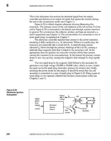
This is the subsystem that receives the electrical signal from the engine
controller and delivers as its output the spark that ignites the mixture during
the end of the compression stroke (see Chapter 1).
Figure 6.29 is a block diagram schematic drawing illustrating this
subsystem. The primary circuit of the coil (depicted as the left portion P of the
coil in Figure 6.29) is connected to the battery and through a power transistor
to ground. For convenience, the collector, emitter, and base are denoted c, e,
and b respectively (see Chapter 3). The coil secondary S is connected to one or
more spark plugs, as explained in Chapter 7.
The electronic controller supplies base current to the power transistor,
rendering it fully conductive (i.e., in saturation). When it is conducting, the
transistor acts essentially like a closed switch. A relatively large current
(denoted I ) flows through the primary windings of the coil (P), creating a
p
relatively large magnetic field that is linked to the secondary coil. At the
appropriate time for ignition the controller switches off the base current,
causing the transistor to be nonconducting. At this instant the primary current
drops to zero very quickly, causing the magnetic field strength to drop rapidly
also.
The very rapid drop in the magnetic field (linked to the secondary S)
generates a very high voltage (30,000 to 50,000 volts), which, in turn, creates
the spark across the spark plug electrodes, igniting the mixture and, finally,
initiating the power stroke for the engine. It should be noted that the coil
secondary is connected to a pair of spark plugs in Figure 6.29. Firing a pair of
spark plugs on two separate cylinders has become commonplace today (see
Chapters 1 and 7).
Figure 6.29
Electronic Ignition
Subsystem
220 UNDERSTANDING AUTOMOTIVE ELECTRONICS