Page 243 - Understanding Automotive Electronics
P. 243

2735 | CH 7  Page 230  Tuesday, March 10, 1998  1:15 PM


                7                     DIGITAL ENGINE CONTROL SYSTEM
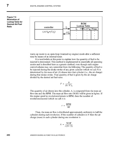


                Figure 7.3
                Illustration of
                Lookup Table for
                Desired Air/Fuel
                Ratio


                                      warm-up mode to an open-loop (warmed-up engine) mode after a sufficient
                                      time by means of an internal timer.
                                          It is worthwhile at this point to explain how the quantity of fuel to be
                                      injected is determined. This method is implemented in essentially all operating
                                      modes and is described here as a generic method, even though each engine
                                      control scheme may vary somewhat from the following. The quantity of fuel to
                                      be injected during the intake stroke of any given cylinder (which we call F) is
                                      determined by the mass of air (A) drawn into that cylinder (i.e., the air charge)
                                      during that intake stroke. That quantity of fuel is given by the air charge
                                      divided by the desired air/fuel ratio:

                                                                         A
                                                                  F =  -----------------
                                                                      ( AF ) d
                                                                         ⁄
                                      The quantity of air drawn into the cylinder, A, is computed from the mass air
                                      flow rate and the RPM. The mass air flow rate (MAF) will be given in kg/sec. If
                                      the engine speed in revolutions/minute is RPM, then the number of
                                      revolutions/second (which we call r) is

                                                                       RPM
                                                                   r =  ------------
                                                                        60

                                          Then, the mass air flow is distributed approximately uniformly to half the
                                      cylinders during each revolution. If the number of cylinders is N then the air
                                      charge (mass) in each cylinder during one revolution is

                                                                       MAF
                                                                 A =  ------------------
                                                                          ⁄
                                                                      rN 2)
                                                                       (

                230                   UNDERSTANDING AUTOMOTIVE ELECTRONICS
   238   239   240   241   242   243   244   245   246   247   248