
Page 241 - Understanding Automotive Electronics
P. 241
2735 | CH 7 Page 228 Tuesday, March 10, 1998 1:15 PM
7 DIGITAL ENGINE CONTROL SYSTEM
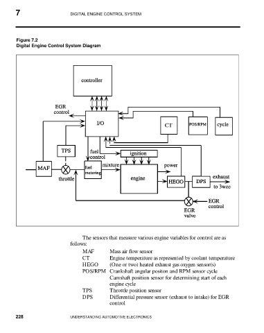
Figure 7.2
Digital Engine Control System Diagram
The sensors that measure various engine variables for control are as
follows:
MAF Mass air flow sensor
CT Engine temperature as represented by coolant temperature
HEGO (One or two) heated exhaust gas oxygen sensor(s)
POS/RPM Crankshaft angular positon and RPM sensor cycle
Camshaft position sensor for determining start of each
engine cycle
TPS Throttle position sensor
DPS Differential pressure sensor (exhaust to intake) for EGR
control
228 UNDERSTANDING AUTOMOTIVE ELECTRONICS