
Page 291 - Understanding Automotive Electronics
P. 291
2735 | CH 8 Page 278 Tuesday, March 10, 1998 1:19 PM
8 VEHICLE MOTION CONTROL
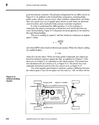
given low-friction condition. The physical configuration for an ABS is shown in
Figure 8.12. In addition to the normal brake components, including brake
pedal, master cylinder, vacuum boost, wheel cylinders, calipers/disks, and brake
lines, this system has a set of angular speed sensors at each wheel, an electronic
control module, and a hydraulic brake pressure modulator (regulator).
In order to understand the ABS operation, it is first necessary to
understand the physical mechanism of wheel lock and vehicle skid that can
occur during braking. Figure 8.13 illustrates the forces applied to the wheel by
the road during braking.
The car is traveling at a speed U and the wheels are rotating at an angular
speed w where
πRPM
w = ----------------
30
and where RPM is the wheel revolutions per minute. When the wheel is rolling
(no applied brakes),
U = Rw
where R is the tire radius. When the brake pedal is depressed, the calipers are
forced by hydraulic pressure against the disk, as explained in Chapter 1. This
force acts as a torque T in opposition to the wheel rotation. The actual force
b
that decelerates the car is shown as F in Figure 8.13. The lateral force that
b
maintains directional control of the car is shown as F in Figure 8.13.
L
The wheel angular speed begins to decrease, causing a difference between
the vehicle speed U and the tire speed over the road (i.e., wR). In effect, the tire
Figure 8.12
Antilock Braking
System
FPO
278 UNDERSTANDING AUTOMOTIVE ELECTRONICS