
Page 295 - Understanding Automotive Electronics
P. 295
2735 | CH 8 Page 282 Tuesday, March 10, 1998 1:19 PM
8 VEHICLE MOTION CONTROL
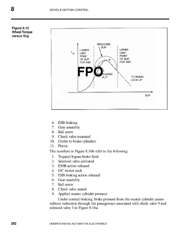
Figure 8.15
Wheel Torque
versus Slip
FPO
6. ESB braking
7. Gear assembly
8. Ball screw
9. Check valve unseated
10. Outlet to brake cylinders
11. Piston
The numbers in Figure 8.16b refer to the following:
1. Trapped bypass brake fluid
2. Solenoid valve activated
3. EMB action released
4. DC motor pack
5. ESB braking action released
6. Gear assembly
7. Ball screw
8. Check valve seated
9. Applied master cylinder pressure
Under normal braking, brake pressure from the master cylinder passes
without reduction through the passageways associated with check valve 9 and
solenoid valve 3 in Figure 8.16a.
282 UNDERSTANDING AUTOMOTIVE ELECTRONICS