
Page 395 - Understanding Automotive Electronics
P. 395
2735 | CH 11 Page 382 Tuesday, March 10, 1998 1:30 PM
11 FUTURE AUTOMOTIVE ELECTRONIC SYSTEMS
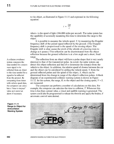
to the object, as illustrated in Figure 11.11 and expressed in the following
equation:
2R
t = ------
c
where c is the speed of light (186,000 miles per second). The radar system has
the capability of accurately measuring this time to determine the range to the
object.
It is possible to measure the vehicle speed, V, by measuring the Doppler
frequency shift of the pulsed signal reflected by the ground. (The Doppler
frequency shift is proportional to the speed of the moving object. The
Doppler shift is what causes the pitch of the whistle of a moving train to
change as it passes.) This reflection can be discriminated from the object
reflection because the ground reflection is at a low angle and a short, fixed
range.
A collision avoidance The reflection from an object will have a pulse shape that is very nearly
system compares the identical to that of the transmitted pulse. As noted, the radar system can
time needed for a micro- detect this object reflection and find R to determine the distance from the
wave signal to be vehicle to the object. In addition, the relative speed of closure between the car
reflected from an object and the object can be calculated by adding the vehicle speed, V, from the
to the time needed for a ground reflected pulses and the speed of the object, S, which can be
signal to be reflected determined from the change in range of the object’s reflection pulses. A block
from the ground. By diagram of an experimental collision warning system is shown in Figure
comparing these times 11.12. In this system, the range, R, to the object and the closing speed, V + S,
with vehicle speed data, are measured.
the computer can calcu- The computer can perform a number of calculations on this data. For
late a “time to impact” example, the computer can calculate the time to collision, T. Whenever this
value and sound an time is less than a preset value, a visual and audible warning is generated. The
alarm if necessary. system could also be programmed to release the throttle and apply the brakes, if
automatic control were desired.
Figure 11.11
Range to Object for
Anticollision
Warning System
FPO
382 UNDERSTANDING AUTOMOTIVE ELECTRONICS