
Page 400 - Understanding Automotive Electronics
P. 400
2735 | CH 11 Page 387 Tuesday, March 10, 1998 1:30 PM
FUTURE AUTOMOTIVE ELECTRONIC SYSTEMS 11
description of the CRT display in Chapter 9. It was also speculated that the
CRT might be used in conjunction with a heads up display (HUD). There is
no clear sign, however, that the basic display source will be a CRT. In fact, any
light-emitting display device can be used with a HUD. A heads up display of
the speed is now available on certain models of automobiles.
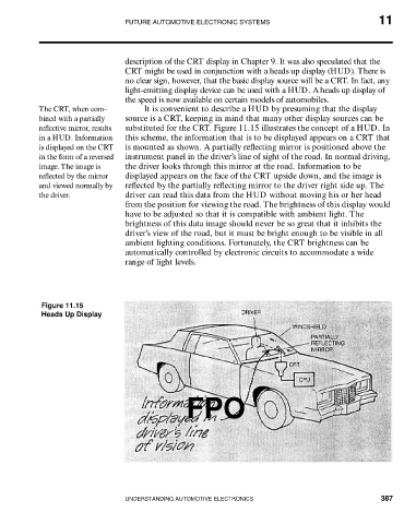
The CRT, when com- It is convenient to describe a HUD by presuming that the display
bined with a partially source is a CRT, keeping in mind that many other display sources can be
reflective mirror, results substituted for the CRT. Figure 11.15 illustrates the concept of a HUD. In
in a HUD. Information this scheme, the information that is to be displayed appears on a CRT that
is displayed on the CRT is mounted as shown. A partially reflecting mirror is positioned above the
in the form of a reversed instrument panel in the driver’s line of sight of the road. In normal driving,
image. The image is the driver looks through this mirror at the road. Information to be
reflected by the mirror displayed appears on the face of the CRT upside down, and the image is
and viewed normally by reflected by the partially reflecting mirror to the driver right side up. The
the driver. driver can read this data from the HUD without moving his or her head
from the position for viewing the road. The brightness of this display would
have to be adjusted so that it is compatible with ambient light. The
brightness of this data image should never be so great that it inhibits the
driver’s view of the road, but it must be bright enough to be visible in all
ambient lighting conditions. Fortunately, the CRT brightness can be
automatically controlled by electronic circuits to accommodate a wide
range of light levels.
Figure 11.15
Heads Up Display
FPO
UNDERSTANDING AUTOMOTIVE ELECTRONICS 387