
Page 402 - Understanding Automotive Electronics
P. 402
2735 | CH 11 Page 389 Tuesday, March 10, 1998 1:30 PM
FUTURE AUTOMOTIVE ELECTRONIC SYSTEMS 11
CPU. However, each sensor only communicates periodically with the computer
for a short time interval during sampling.
Sensor multiplexing can It is possible to connect all the sensors to the CPU with only a single wire
reduce the necessary wir- (with ground return, of course). This wire, which can be called a data bus,
ing in an electrical har- provides the communication link between all of the sensors and the CPU. Each
ness by using time sensor would have exclusive use of this bus to send data (i.e., measurement of
division multiplexing. the associated engine variable or parameter) during its time slot. A separate time
slot would be provided for each sensor.
This process of selectively assigning the data bus exclusively to a specific
sensor during its time slot is called time division multiplexing (or sometimes just
multiplexing—MUX). Recall that multiplexing was discussed as a data selector
for the CPU input and output in a digital instrumentation system as described
in Chapter 9. Limited use of multiplexing already exists in some production
cars, but the concept considered here is for data flow throughout the entire car
between all electronic subsystems.
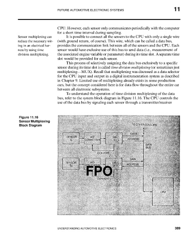
To understand the operation of time division multiplexing of the data
bus, refer to the system block diagram in Figure 11.16. The CPU controls the
use of the data bus by signaling each sensor through a transmitter/receiver
Figure 11.16
Sensor Multiplexing
Block Diagram
FPO
UNDERSTANDING AUTOMOTIVE ELECTRONICS 389