
Page 403 - Understanding Automotive Electronics
P. 403
2735 | CH 11 Page 390 Tuesday, March 10, 1998 1:30 PM
11 FUTURE AUTOMOTIVE ELECTRONIC SYSTEMS
(T/R) unit. Whenever the CPU requires data from any sensor, it sends a coded
message on the bus, which is connected to all T/R units. However, the message
consists of a sequence of binary voltage pulses that are coded for the particular
T/R unit. A T/R unit responds only to one particular sequence of pulses, which
can be thought of as the address for that unit.
Each sensor in a multi- Whenever a T/R unit receives data corresponding to its address, it
plexing system sends its activates an analog-to-digital converter. The sensor’s analog output at this
individual data over a instant is converted to a digital binary number as already discussed. This
common bus. The com- number and the T/R unit’s address are included so that the CPU can identify
puter identifies the sen- the source of the data. Thus, the CPU interrogates a particular sensor and then
sor by signaling each receives the measurement data from the sensor on the data bus. The CPU then
sensor with a unique sends out the address of the next T/R unit whose sensor is to be sampled.
address.
Control Signal Multiplexing
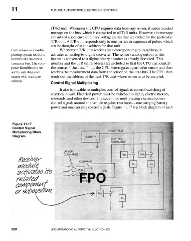
It also is possible to multiplex control signals to control switching of
electrical power. Electrical power must be switched to lights, electric motors,
solenoids, and other devices. The system for multiplexing electrical power
control signals around the vehicle requires two buses—one carrying battery
power and one carrying control signals. Figure 11.17 is a block diagram of such
Figure 11.17
Control Signal
Multiplexing Block
Diagram
FPO
390 UNDERSTANDING AUTOMOTIVE ELECTRONICS