
Page 144 - Uninterruptible Power Supplies
P. 144
Static Uninterruptible Power Supplies
142 Chapter Five
reduced and reliability figures now quoted are some 10 years mean
time between failure for a single module. Note this figure does not
allow for battery reliability. Figures for a multimodule parallel redun-
dant system are subject to variations and circuit complexity, but as a
guide 20 years is achievable.
Basic Design
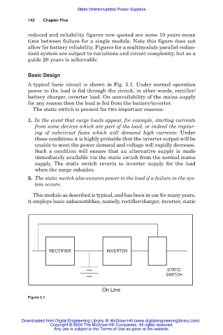
A typical basic circuit is shown in Fig. 5.1. Under normal operation
power to the load is fed through the circuit, in other words, rectifier/
battery charger, inverter load. On unavailability of the mains supply
for any reason then the load is fed from the battery/inverter.
The static switch is present for two important reasons:
1. In the event that surge loads appear, for example, starting currents
from some devices which are part of the load, or indeed the ruptur-
ing of subcircuit fuses which will demand high currents: Under
these conditions it is highly probable that the inverter output will be
unable to meet the power demand and voltage will rapidly decrease.
Such a condition will ensure that an alternative supply is made
immediately available via the static switch from the normal mains
supply. The static switch reverts to inverter supply for the load
when the surge subsides.
2. The static switch also ensures power to the load if a failure in the sys-
tem occurs.
This module as described is typical, and has been in use for many years,
it employs basic subassemblies, namely, rectifier/charger, inverter, static
RECTIFIER INVERTER
STATIC
SWITCH
On Line
Figure 5.1
Downloaded from Digital Engineering Library @ McGraw-Hill (www.digitalengineeringlibrary.com)
Copyright © 2004 The McGraw-Hill Companies. All rights reserved.
Any use is subject to the Terms of Use as given at the website.