
Page 148 - Uninterruptible Power Supplies
P. 148
Static Uninterruptible Power Supplies
146 Chapter Five
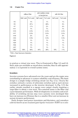
with rectifier choke
without filter with 5th filter
or transformer
Half Load Full Load Half Load Full Load Half Load Full Load
H3 1% 1% 1%
H5 41% 28% 3%
H7 11% 2% 4%
H11 7% 7% 7%
H13 2.5% 2.5% 2.5%
H17 2.5% 2.5% 2.5%
H19 2% 2% 2%
H23 2.5% 2.5% 2.5%
H25 1% 1% 1%
H29 1% 1% 1%
H35 1% 1% 1%
H37 1% 1% 1%
THD* 59% 43% 44% 30% 18% 11%
*THD = Total Harmonic Distortion
Figure 5.4
to produce a virtual sine wave. This is illustrated in Figs. 5.5 and 5.6.
Such units are available as stand-alone modules; they do add approxi-
mately 1 to 2 percent to overall system losses.
Inverters
Inverter systems have advanced over the years and are the major area
contributing to advances in system reliability and efficiency. The basic
design is a simple bridge switching circuit (see Fig. 5.7a). Clearly the
switches utilized a variety of solid-state switches and as such devices
increased in performance so the inverter developed. In Fig. 5.7b the
earlier circuits resulted in a square wave output clearly requiring a
large filter to obtain a sine wave. This entailed losses in the filter and
a poor dynamic performance. With developments in circuitry and avail-
ability of switching devices step wave systems were developed that
have an increase in efficiency due to a smaller filter and an increase in
system dynamic performance.
Early designs used power transistors and thyristors, and nowadays
a device known as an insulated gate bipolar transistor (IGBT) is in com-
Downloaded from Digital Engineering Library @ McGraw-Hill (www.digitalengineeringlibrary.com)
Copyright © 2004 The McGraw-Hill Companies. All rights reserved.
Any use is subject to the Terms of Use as given at the website.