
Page 150 - Uninterruptible Power Supplies
P. 150
Static Uninterruptible Power Supplies
148 Chapter Five
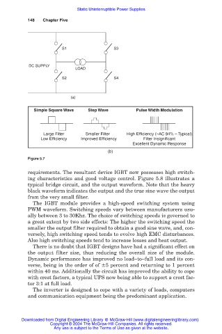
S1 S3
DC SUPPLY
LOAD
S2 S4
(a)
Simple Square Wave Step Wave Pulse Width Modulation
Large Filter Smaller Filter High Efficiency (–AC 94% – Typical)
Low Efficiency Improved Efficiency Filter Insignificant
Excellent Dynamic Response
(b)
Figure 5.7
requirements. The resultant device IGBT now possesses high switch-
ing characteristics and good voltage control. Figure 5.8 illustrates a
typical bridge circuit, and the output waveform. Note that the heavy
black waveform indicates the output and the true sine wave the output
from the very small filter.
The IGBT module provides a high-speed switching system using
PWM waveform. Switching speeds vary between manufacturers usu-
ally between 3 to 30Khz. The choice of switching speeds is governed to
a great extent by two side effects: The higher the switching speed the
smaller the output filter required to obtain a good sine wave, and, con-
versely, high switching speed tends to evolve high EMC disturbances.
Also high switching speeds tend to increase losses and heat output.
There is no doubt that IGBT designs have had a significant effect on
the output filter size, thus reducing the overall size of the module.
Dynamic performance has improved no load–to–full load and its con-
verse, being in the order of of 5 percent and returning to 1 percent
within 40 ms. Additionally the circuit has improved the ability to cope
with crest factors, a typical UPS now being able to support a crest fac-
tor 3:1 at full load.
The inverter is designed to cope with a variety of loads, computers
and communication equipment being the predominant application.
Downloaded from Digital Engineering Library @ McGraw-Hill (www.digitalengineeringlibrary.com)
Copyright © 2004 The McGraw-Hill Companies. All rights reserved.
Any use is subject to the Terms of Use as given at the website.