
Page 197 - Uninterruptible Power Supplies
P. 197
Batteries
Batteries 195
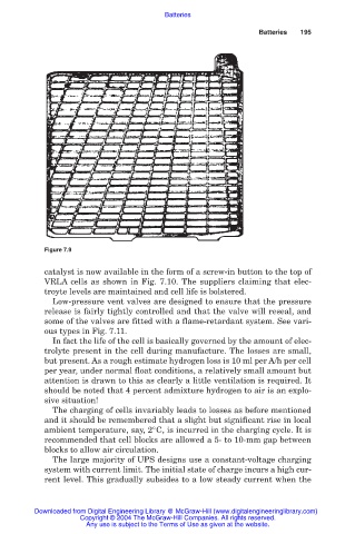
Figure 7.9
catalyst is now available in the form of a screw-in button to the top of
VRLA cells as shown in Fig. 7.10. The suppliers claiming that elec-
troyte levels are maintained and cell life is bolstered.
Low-pressure vent valves are designed to ensure that the pressure
release is fairly tightly controlled and that the valve will reseal, and
some of the valves are fitted with a flame-retardant system. See vari-
ous types in Fig. 7.11.
In fact the life of the cell is basically governed by the amount of elec-
trolyte present in the cell during manufacture. The losses are small,
but present. As a rough estimate hydrogen loss is 10 ml per A/h per cell
per year, under normal float conditions, a relatively small amount but
attention is drawn to this as clearly a little ventilation is required. It
should be noted that 4 percent admixture hydrogen to air is an explo-
sive situation!
The charging of cells invariably leads to losses as before mentioned
and it should be remembered that a slight but significant rise in local
ambient temperature, say, 2°C, is incurred in the charging cycle. It is
recommended that cell blocks are allowed a 5- to 10-mm gap between
blocks to allow air circulation.
The large majority of UPS designs use a constant-voltage charging
system with current limit. The initial state of charge incurs a high cur-
rent level. This gradually subsides to a low steady current when the
Downloaded from Digital Engineering Library @ McGraw-Hill (www.digitalengineeringlibrary.com)
Copyright © 2004 The McGraw-Hill Companies. All rights reserved.
Any use is subject to the Terms of Use as given at the website.