
Page 61 - Urban water supply handbook
P. 61
URBAN WATER INFRASTRUCTURE: A HISTORICAL PERSPECTIVE
1.60 HISTORY, PLANNING, OUTSOURCING
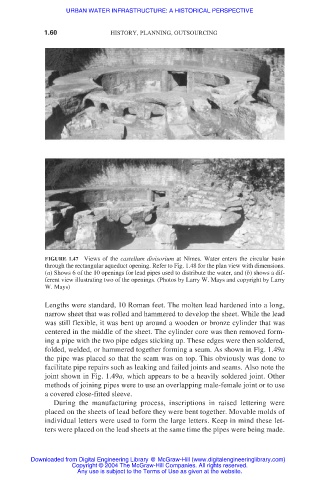
FIGURE 1.47 Views of the castellum divisorium at Nîmes. Water enters the circular basin
through the rectangular aqueduct opening. Refer to Fig. 1.48 for the plan view with dimensions.
(a) Shows 6 of the 10 openings for lead pipes used to distribute the water, and (b) shows a dif-
ferent view illustrating two of the openings. (Photos by Larry W. Mays and copyright by Larry
W. Mays)
Lengths were standard, 10 Roman feet. The molten lead hardened into a long,
narrow sheet that was rolled and hammered to develop the sheet. While the lead
was still flexible, it was bent up around a wooden or bronze cylinder that was
centered in the middle of the sheet. The cylinder core was then removed form-
ing a pipe with the two pipe edges sticking up. These edges were then soldered,
folded, welded, or hammered together forming a seam. As shown in Fig. 1.49a
the pipe was placed so that the seam was on top. This obviously was done to
facilitate pipe repairs such as leaking and failed joints and seams. Also note the
joint shown in Fig. 1.49a, which appears to be a heavily soldered joint. Other
methods of joining pipes were to use an overlapping male-female joint or to use
a covered close-fitted sleeve.
During the manufacturing process, inscriptions in raised lettering were
placed on the sheets of lead before they were bent together. Movable molds of
individual letters were used to form the large letters. Keep in mind these let-
ters were placed on the lead sheets at the same time the pipes were being made.
Downloaded from Digital Engineering Library @ McGraw-Hill (www.digitalengineeringlibrary.com)
Copyright © 2004 The McGraw-Hill Companies. All rights reserved.
Any use is subject to the Terms of Use as given at the website.