
Page 62 - Urban water supply handbook
P. 62
URBAN WATER INFRASTRUCTURE: A HISTORICAL PERSPECTIVE
URBAN WATER INFRASTRUCTURE 1.61
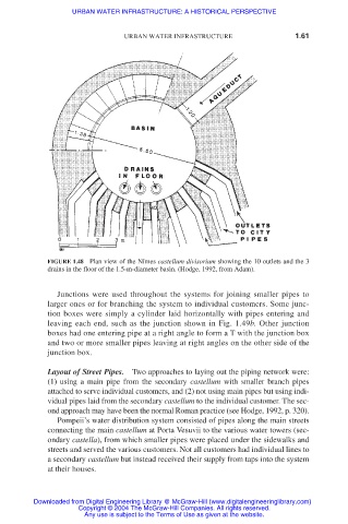
FIGURE 1.48 Plan view of the Nîmes castellum divisorium showing the 10 outlets and the 3
drains in the floor of the 1.5-m-diameter basin. (Hodge, 1992, from Adam).
Junctions were used throughout the systems for joining smaller pipes to
larger ones or for branching the system to individual customers. Some junc-
tion boxes were simply a cylinder laid horizontally with pipes entering and
leaving each end, such as the junction shown in Fig. 1.49b. Other junction
boxes had one entering pipe at a right angle to form a T with the junction box
and two or more smaller pipes leaving at right angles on the other side of the
junction box.
Layout of Street Pipes. Two approaches to laying out the piping network were:
(1) using a main pipe from the secondary castellum with smaller branch pipes
attached to serve individual customers, and (2) not using main pipes but using indi-
vidual pipes laid from the secondary castellum to the individual customer. The sec-
ond approach may have been the normal Roman practice (see Hodge, 1992, p. 320).
Pompeii’s water distribution system consisted of pipes along the main streets
connecting the main castellum at Porta Vesuvii to the various water towers (sec-
ondary castella), from which smaller pipes were placed under the sidewalks and
streets and served the various customers. Not all customers had individual lines to
a secondary castellum but instead received their supply from taps into the system
at their houses.
Downloaded from Digital Engineering Library @ McGraw-Hill (www.digitalengineeringlibrary.com)
Copyright © 2004 The McGraw-Hill Companies. All rights reserved.
Any use is subject to the Terms of Use as given at the website.