
Page 36 - Using ANSYS for Finite Element Analysis Dynamic, Probabilistic, Design and Heat Transfer Analysis
P. 36
composite materials • 23
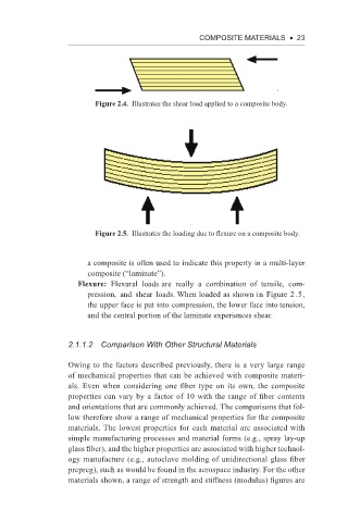
Figure 2.4. Illustrates the shear load applied to a composite body.
Figure 2.5. Illustrates the loading due to flexure on a composite body.
a composite is often used to indicate this property in a multi-layer
composite (“laminate”).
Flexure: Flexural loads are really a combination of tensile, com-
pression, and shear loads. When loaded as shown in Figure 2.5,
the upper face is put into compression, the lower face into tension,
and the central portion of the laminate experiences shear.
2.1.1.2 Comparison With other Structural Materials
Owing to the factors described previously, there is a very large range
of mechanical properties that can be achieved with composite materi-
als. Even when considering one fiber type on its own, the composite
properties can vary by a factor of 10 with the range of fiber contents
and orientations that are commonly achieved. The comparisons that fol-
low therefore show a range of mechanical properties for the composite
materials. The lowest properties for each material are associated with
simple manufacturing processes and material forms (e.g., spray lay-up
glass fiber), and the higher properties are associated with higher technol-
ogy manufacture (e.g., autoclave molding of unidirectional glass fiber
prepreg), such as would be found in the aerospace industry. For the other
materials shown, a range of strength and stiffness (modulus) figures are