
Page 144 - Using ANSYS for Finite Element Analysis A Tutorial for Engineers
P. 144
stAtIc AnAlysIs usIng AreA elements • 131
And, check the SEQV (equivalent stress / von Mises stress) for the
node in question. (as shown in red as follows).
The equivalent stress was found to be 2.9141MPa at this point. We
will use smaller elements to try to get a more accurate solution.
14. Resize elements:
To change the element size, we need to go back to the Preprocessor
menu
Preprocessor > Meshing > Size Cntrls > Manual Size >
Areas > All Areas
Now decrease the element edge length (i.e., 20).
Now remesh the model:
Preprocessor > Meshing > Mesh > Areas > Free
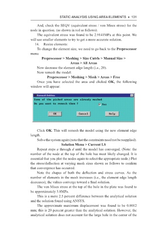
Once you have selected the area and clicked OK, the following
window will appear:
Click OK. This will remesh the model using the new element edge
length.
Solve the system again (note that the constraints need not be reapplied).
Solution Menu > Current LS
Repeat steps a through d until the model has converged. (Note: the
number of the node at the top of the hole has most likely changed. It is
essential that you plot the nodes again to select the appropriate node.) Plot
the stress/deflection at varying mesh sizes shown as follows to confirm
that convergence has occurred.
Note the shapes of both the deflection and stress curves. As the
number of elements in the mesh increases (i.e., the element edge length
decreases), the values converge toward a final solution.
The von Mises stress at the top of the hole in the plate was found to
be approximately 3.8MPa.
This is a mere 2.5 percent difference between the analytical solution
and the solution found using ANSYS.
The approximate maximum displacement was found to be 0.0012
mm; this is 20 percent greater than the analytical solution. However, the
analytical solution does not account for the large hole in the center of the