
Page 147 - Using ANSYS for Finite Element Analysis A Tutorial for Engineers
P. 147
134 • Using ansys for finite element analysis
You can list the von Mises stresses to verify the results at certain
nodes:
General Postproc > List Results
Select:
Stress, Principals SPRIN
Bracket Example
Now we will return to the analysis of the bracket. A combination of GUI
and the command line will be used for this example. The problem to be
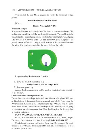
modeled in this example is a simple bracket shown in the following figure.
This bracket is to be built from a 20 mm-thick steel plate. A figure of the
plate is shown as follows. This plate will be fixed at the two small holes on
the left and have a load applied to the larger hole on the right.
Preprocessing: Defining the Problem
1. Give the bracket example a title:
Utility Menu > File > Change Title
2. Form the geometry:
Again, Boolean operations will be used to create the basic geometry
of the bracket.
Create the main rectangular shape.
The main rectangular shape has a width of 80 mm, a height of 100 mm,
and the bottom-left corner is located at coordinates (0,0). Ensure that the
Preprocessor menu is open. (Alternatively, type /PREP7 into the com-
mand line window.) Now instead of using the GUI window, we are going
to enter code into the command line. Now, I will explain the line required
to create a rectangle:
BLC4, XCORNER, YCORNER, WIDTH, HEIGHT
BLC4, X coord (bottom left), Y coord (bottom left), width, height.
Therefore, the command line for this rectangle is BLC4,0,0,80,100.
Create the circular end on the right-hand side. The center of the circle
is located at (80,50) and has a radius of 50 mm. The following code is used
to create a circular area: