
Page 167 - Using ANSYS for Finite Element Analysis A Tutorial for Engineers
P. 167
154 • Using ansys for finite element analysis
and the deformed shape of given extrusion-die assembly, under give pres-
sure loading and boundary condition.
Material properties: E = 5 × 10⁶ MPa, ν = 0.15
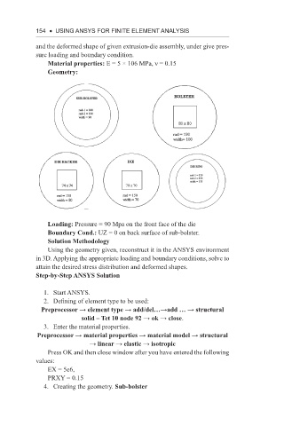
Geometry:
Loading: Pressure = 90 Mpa on the front face of the die
Boundary Cond.: UZ = 0 on back surface of sub-bolster.
Solution Methodology
Using the geometry given, reconstruct it in the ANSYS environment
in 3D. Applying the appropriate loading and boundary conditions, solve to
attain the desired stress distribution and deformed shapes.
Step-by-Step ANSYS Solution
1. Start ANSYS.
2. Defining of element type to be used:
Preprocessor → element type → add/del…→add … → structural
solid – Tet 10 node 92 → ok → close.
3. Enter the material properties.
Preprocessor → material properties → material model → structural
→ linear → elastic → isotropic
Press OK and then close window after you have entered the following
values:
EX = 5e6,
PRXY = 0.15
4. Creating the geometry. Sub-bolster