
Page 172 - Using ANSYS for Finite Element Analysis A Tutorial for Engineers
P. 172
stAtIc AnAlysIs usIng Volume elements • 159
Having completed the preprocessor phase, we now move to the
solution phase. Go to the ANSYS main menu and click on solution.
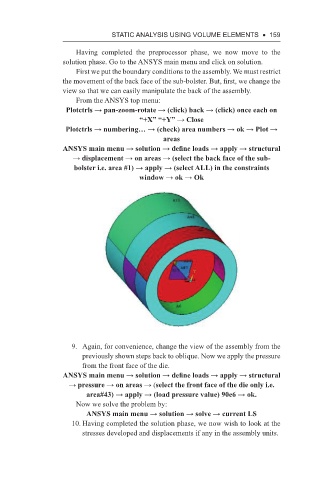
First we put the boundary conditions to the assembly. We must restrict
the movement of the back face of the sub-bolster. But, first, we change the
view so that we can easily manipulate the back of the assembly.
From the ANSYS top menu:
Plotctrls → pan-zoom-rotate → (click) back → (click) once each on
“+X” “+Y” → Close
Plotctrls → numbering… → (check) area numbers → ok → Plot →
areas
ANSYS main menu → solution → define loads → apply → structural
→ displacement → on areas → (select the back face of the sub-
bolster i.e. area #1) → apply → (select ALL) in the constraints
window → ok → Ok
9. Again, for convenience, change the view of the assembly from the
previously shown steps back to oblique. Now we apply the pressure
from the front face of the die.
ANSYS main menu → solution → define loads → apply → structural
→ pressure → on areas → (select the front face of the die only i.e.
area#43) → apply → (load pressure value) 90e6 → ok.
Now we solve the problem by:
ANSYS main menu → solution → solve → current LS
10. Having completed the solution phase, we now wish to look at the
stresses developed and displacements if any in the assembly units.