
Page 199 - Valve Selection Handbook
P. 199
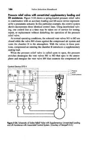
186                  Valve  Selection  Handbook

             Pressure  relief valves  with  unrestricted  supplementary  loading  and
             lift  assistance.  Figure  5-24 shows a  spring-loaded  pressure  relief  valve
            in combination with an auxiliary loading and lift-assist  device  represent-
            ed by a pneumatic actuator. In this particular example, the control system
            shown  incorporates three  identical  control  lines. Using interlocked  valv-
            ing,  one  control  line  at  a  time  may  be  taken  out  of  service  for  testing,
            repair,  or  replacement  without disturbing the  operation  of  the  pressure
            relief valve.
               At normal operating conditions, the solenoid vent valves Ml  to M3 are
            closed  while the valve M4 closes  against the compressed  air  system and
            vents  the  chamber  H  to  the  atmosphere.  With the  valves in  these  posi-
            tions, compressed  air entering the chamber B introduces a supplementary
            seating load.
               When  the  pressure  relief  valve  is  called  upon  to  open,  the pressure
            switches  deenergize  the  vent valves Ml  to  M3  that  open  to  the  atmos-
            phere  and  energize  the  vent valve M4  that connects  the  compressed  air


            Figure 5-24. Schematic of Safety Relief Valve with Supplementary Unrestricted Loading
            and  Lift Assistance with Associated Control  System. (Courtesy of Sempell A.G.)