
Page 197 - Valve Selection Handbook
P. 197
184 Valve Selection Handbook
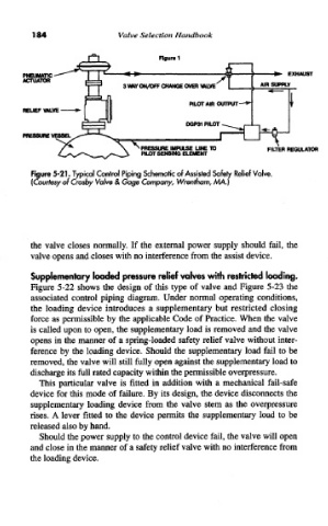
Figure 5-21. Typical Control Piping Schematic of Assisted Safety Relief Valve.
(Courtesy of Crosby Valve & Gage Company, Wrentham, MA.)
the valve closes normally. If the external power supply should fail, the
valve opens and closes with no interference from the assist device.
Supplementary loaded pressure relief valves with restricted loading.
Figure 5-22 shows the design of this type of valve and Figure 5-23 the
associated control piping diagram. Under normal operating conditions,
the loading device introduces a supplementary but restricted closing
force as permissible by the applicable Code of Practice. When the valve
is called upon to open, the supplementary load is removed and the valve
opens in the manner of a spring-loaded safety relief valve without inter-
ference by the loading device. Should the supplementary load fail to be
removed, the valve will still fully open against the supplementary load to
discharge its full rated capacity within the permissible overpressure.
This particular valve is fitted in addition with a mechanical fail-safe
device for this mode of failure. By its design, the device disconnects the
supplementary loading device from the valve stem as the overpressure
rises. A lever fitted to the device permits the supplementary load to be
released also by hand.
Should the power supply to the control device fail, the valve will open
and close in the manner of a safety relief valve with no interference from
the loading device.