
Page 192 - Valve Selection Handbook
P. 192
Pressure Relief Valves 179
Figure 5-14 shows a balanced liquid relief valve in which the stem car-
rying the disc is fitted with two O-ring seals. The lower O-ring seal
serves as a drag ring that is energized by the inlet pressure through bore
holes in disc and stem. The frictional resistance by this ring during open-
ing and closing prevents uncontrolled chatter of the valve. The upper O-
ring serves as a balanced seal against back pressure. A hole in the bonnet
serves as a vent in case of leakage past the seal.
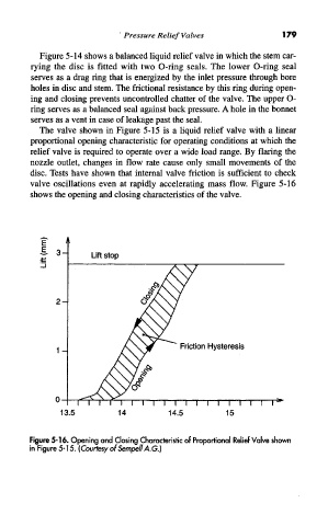
The valve shown in Figure 5-15 is a liquid relief valve with a linear
proportional opening characteristic for operating conditions at which the
relief valve is required to operate over a wide load range. By flaring the
nozzle outlet, changes in flow rate cause only small movements of the
disc. Tests have shown that internal valve friction is sufficient to check
valve oscillations even at rapidly accelerating mass flow. Figure 5-16
shows the opening and closing characteristics of the valve.
Figure 5-16. Opening and Closing Characteristic of Proportional Relief Valve shown
in Figure 5-15. (Courtesy of Sempell A.G.)