
Page 190 - Valve Selection Handbook
P. 190
Pressure Relief Valves 177
Liquid Relief Valves
Normally, liquid relief valves differ from conventional safety relief
valves only in a slight modification of the geometry around the disc to
achieve a specific performance in liquid service. The valves shown in
Figure 5-13 through Figure 5-15 represent a small selection of liquid
relief valves offered by the industry.
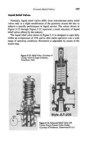
The liquid relief valve shown in Figure 5-13 is designed to open fully
within an overpressure of 10% and to offer stable operation over a wide
range of operating conditions. Blowdown is adjustable by means of the
nozzle ring.
Figure 5-13. Relief Valve. (Courtesy of
Crosby Valve & Gage Company,
Wrentham, MA.)
Figure 5-14. Balanced Relief Valve with
Friction Ring to Prevent Valve Chatter.
(Courtesy or Anderson, Greenwood & Co.)