
Page 189 - Valve Selection Handbook
P. 189
176 Valve Selection Handbook
disc holder to counter the possible adverse effect of inlet pressure loss on
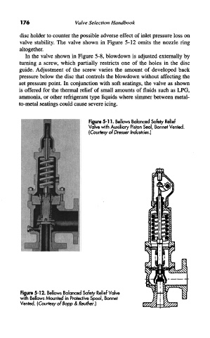
valve stability. The valve shown in Figure 5-12 omits the nozzle ring
altogether.
In the valve shown in Figure 5-8, blowdown is adjusted externally by
turning a screw, which partially restricts one of the holes in the disc
guide. Adjustment of the screw varies the amount of developed back
pressure below the disc that controls the blowdown without affecting the
set pressure point. In conjunction with soft seatings, the valve as shown
is offered for the thermal relief of small amounts of fluids such as LPG,
ammonia, or other refrigerant type liquids where simmer between metal-
to-metal seatings could cause severe icing.
Figure 5-11. Bellows Balanced Safety Relief
Valve with Auxiliary Piston Seal, Bonnet Vented.
(Courtesy of Dresser Industries.)
Figure 5-12. Bellows Balanced Safety Relief Valve
with Bellows Mounted in Protective Spool, Bonnet
Vented. (Courtesy of Bopp & Reuther.)