
Page 188 - Valve Selection Handbook
P. 188
Pressure Relief Valves 175
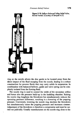
Figure 5-10. Bellows Balanced Safely Relief Valve,
Bonnet Vented. (Courtesy of Sempell A.G.)
ring on the nozzle allows the disc guide to be located away from the
direct impact of the fluid escaping from the nozzle, leading to a robust
construction for process fluids that may carry solids in suspension. In
combination with balanced bellows, guide and valve spring can be com-
pletely isolated from the flowing fluid.
The nozzle ring is used to control the width of the secondary orifice
and hence also the pressure build-up in the huddling chamber. Raising
the nozzle ring lengthens the blowdown but simultaneously reduces the
operating pressure difference, resulting in a lowering of the popping
pressure. Conversely, lowering the nozzle ring shortens the blowdown
but simultaneously raises the popping pressure and increases simmer.
Adjustment of the blowdown is therefore a compromise and must be car-
ried out judicially. Usually manufacturers set the nozzle ring close to the