
Page 212 - Valve Selection Handbook
P. 212
Pressure Relief Valves 199
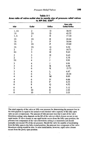
Table 5-1
Area ratio of valve outlet size to nozzle size of pressure relief valves
47
to API Std. 526
Area ratio
Inlet Outlet Orifice Outlet/Orifice
l,l1/2 2 D 30.55
11/2 21/2 D 43.55
1,1/2 2 E 17.14
11/2 21/2 E 24.44
11/2 2 F 10.94
11/2 21/2 F 15.60
11/2 21/2 G 9.52
2 3 G 14.71
11/2 3 H 9.43
2 3 H 9.43
2 3 J 5.75
2 1/2 4 J 9.91
3 4 J 9.91
3 4 K 6.94
3 6 K 15.73
3 4 L 4.47
4 6 L 10.14
4 6 M 8.03
4 6 N 6.66
4 6 P 4.53
6 8 Q 4.52
6 8 R 3.12
6 10 R 4.93
8 10 T 3.03
The rated capacity of the valve at 10% over pressure for determining the pressure loss in
the inlet pipeline is equal to the actual or non-derated valve capacity of the fully open
valve at zero overpressure. The amount of inlet pressure loss that is part of the valve
blowdown setting value depends on the lift of the valve at which closure occurs in one
rapid stroke. If valve closure in one rapid stroke occurs from the fully open position, the
pressure loss component of the valve blowdown setting is a maximum and should
normally not exceed 3% of the set pressure. Should the valve be capable of modulating
from the fully open to the fully closed position, the pressure loss component of the valve
blowdown setting would be zero. In most installations, however, rapid valve closure
occurs from the partly open position.