
Page 207 - Valve Selection Handbook
P. 207
194 Valve Selection Handbook
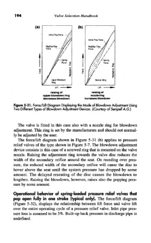
Figure 5-31. Force/Lift Diagram Displaying the Mode of Slowdown Adjustment Using
Two Different Types of Slowdown Adjustment Devices. (Courtesy of Sempell A.G.]
The valve is fitted in this case also with a nozzle ring for blowdown
adjustment. This ring is set by the manufacturers and should not normal-
ly be adjusted by the user.
The force/lift diagram shown in Figure 5-31 (b) applies to pressure
relief valves of the type shown in Figure 5-7. The blowdown adjustment
device consists in this case of a screwed ring that is mounted on the valve
nozzle. Raising the adjustment ring towards the valve disc reduces the
width of the secondary orifice around the seat. On receding over pres-
sure, the reduced width of the secondary orifice will cause the disc to
hover above the seat until the system pressure has dropped by some
amount. The delayed reseating of the disc causes the blowdown to
lengthen. Raising the blowdown, however, raises also the popping pres-
sure by some amount.
Operational behavior of spring-loaded pressure relief valves that
pop open fully in one stroke (typical only). The force/lift diagram
(Figure 5-32), displays the relationship between lift force and valve lift
over the entire operating cycle of a pressure relief valve. Inlet pipe pres-
sure loss is assumed to be 3%. Built-up back pressure in discharge pipe is
undefined.