
Page 206 - Valve Selection Handbook
P. 206
Pressure Relief Valves 193
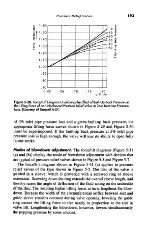
Figure 5-30. Force/Lift Diagram Displaying the Effect of Built-Up Back Pressure on
the Lifting Force of an Unbalanced Pressure Relief Valve at Zero Inlet Line Pressure
Loss. (Courtesy of Sempell A.G.)
of 3% inlet pipe pressure loss and a given built-up back pressure, the
appropriate lifting force curves shown in Figure 5-29 and Figure 5-30
must be superimposed. If the built-up back pressure at 3% inlet pipe
pressure loss is high enough, the valve will lose its ability to open fully
in one stroke.
Modes of blowdown adjustment. The force/lift diagrams (Figure 5-31
(a) and (b)) display the mode of blowdown adjustment with devices that
are typical of pressure relief valves shown in Figure 5-5 and Figure 5-7.
The force/lift diagram shown in Figure 5-31 (a) applies to pressure
relief valves of the type shown in Figure 5-5. Trie disc of the valve is
guided in a sleeve, which is provided with a screwed ring or sleeve
extension. Screwing down the ring extends the overall sleeve length, and
thereby raises the angle of deflection of the fluid acting on the underside
of the disc. The resulting higher lifting force, in turn, lengthens the blow-
down. Because the width of the circumferential orifice between seat and
guide sleeve remains constant during valve opening, lowering the guide
ring causes the lifting force to rise nearly in proportion to the rise in
valve lift. Lengthening the blowdown, however, lowers simultaneously
the popping pressure by some amount.