
Page 249 - Valve Selection Handbook
P. 249
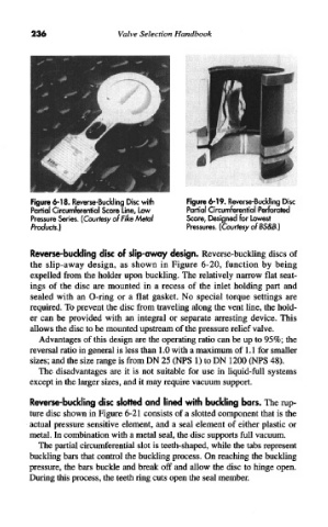
236                   Valve  Selection  Handbook


            Figure 6-18. Reverse-Buckling  Disc with  Figure 6-19. Reverse-Buckling Disc
            Partial Circumferential Score Line, Low  Partial Circumferential  Perforated
            Pressure Series. (Courtesy ofFike Metal  Score, Designed for Lowest
            Products.)                            Pressures. (Courtesy of  BS&B.)


            Reverse-buckling  disc  of  slip-away design.  Reverse-buckling  discs of
            the  slip-away  design,  as  shown  in  Figure  6-20,  function  by  being
            expelled  from  the  holder  upon buckling. The relatively  narrow flat  seat-
            ings  of  the  disc  are  mounted  in  a  recess  of  the  inlet  holding  part  and
            sealed  with  an  O-ring  or  a  flat  gasket.  No  special  torque  settings  are
            required. To prevent the disc from  traveling along the vent line, the hold-
            er  can  be  provided  with  an  integral  or  separate  arresting  device.  This
            allows the disc to be mounted upstream of the pressure relief  valve.
              Advantages of this design are the operating ratio can be up to 95%; the
            reversal ratio in general is less than 1.0 with a maximum of  1.1 for smaller
            sizes; and the size range is from  DN 25 (NFS  1) to DN  1200  (NFS 48).
              The  disadvantages are  it  is  not  suitable  for  use  in  liquid-full  systems
            except in the larger sizes, and it may require vacuum support.

            Reverse-buckling  disc  slotted  and  lined with  buckling bars.  The rup-
            ture disc shown in Figure  6-21  consists of a slotted  component that is the
            actual  pressure  sensitive  element,  and a seal  element  of either  plastic  or
            metal. In combination with a metal seal, the disc supports full vacuum.
              The partial circumferential slot is teeth-shaped, while the tabs represent
            buckling bars that control  the buckling process.  On reaching the buckling
            pressure, the bars buckle and break  off and  allow  the disc  to hinge open.
            During this process, the teeth ring cuts open the seal member.