Page 270 - Valve Selection Handbook
P. 270

Sizing  Pressure Relief  Devices          257


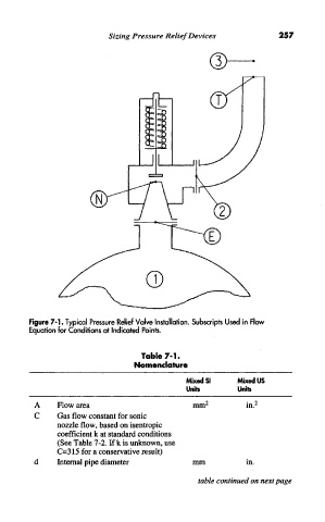
          Figure 7-1. Typical  Pressure  Relief Valve Installation. Subscripts  Used in  Flow
          Equation for Conditions at Indicated Points.

                                     Table  7-1.
                                    Nomenclature
                                                Mixed SI     Mixed US
                                                Units        Units
                                                     2
           A     Flow  area                       mm           in/
           C     Gas flow constant for sonic
                 nozzle flow, based on isentropic
                 coefficient  k at standard conditions
                 (See Table 7-2. If k is unknown, use
                 C=315 for a conservative result)
           d     Internal pipe diameter           mm           in.

                                                   table continued on next page
   265   266   267   268   269   270   271   272   273   274   275