
Page 284 - Valve Selection Handbook
P. 284
Sizing Pressure Relief Devices 271
the set pressure to permit stable valve operation at a blowdown of not
lower than 5%. Consult manufacturer.
SIZING OF INLET PIPING
TO PRESSURE RELIEF VALVES
Codes for the installation of pressure relief valves require that the
cumulative total of non-recoverable pressure losses in the inlet piping to
the pressure relief valves at rated mass flow, including entry loss at the
pressure vessel connection, shall not exceed 3% of the set pressure.
The following procedure permits the estimation of the resistance coef-
ficient of the inlet piping for 3% inlet pressure loss:
1. Initially estimate the resistance coefficient of the proposed inlet
piping.
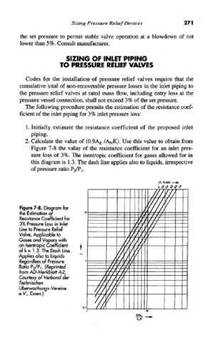
2. Calculate the value of (0.9A E /A NK). Use this value to obtain from
Figure 7-8 the value of the resistance coefficient for an inlet pres-
sure loss of 3%. The isentropic coefficient for gases allowed for in
this diagram is 1.3. The dash line applies also to liquids, irrespective
of pressure ratio P2/Pj.
Figure 7-8. Diagram for
fhe Estimation or
Resistance Coefficient for
3% Pressure Loss in Inlet
Line to Pressure Relief
Valve, Applicable to
Gases and Vapors with
an Isentropic Coefficient
of k = 1.3. The Dash Line
Applies also to Liquids
Regardless of Pressure
Ratio P 2/Pi.(/tepr/ntec/
from AD-Merkblatt A2,
Courtesy of Verband cfer
fecrin/scrien
Uberwach ungs - Vereine
e.V., Essen.)