
Page 287 - Valve Selection Handbook
P. 287
274 Valve Selection Handbook
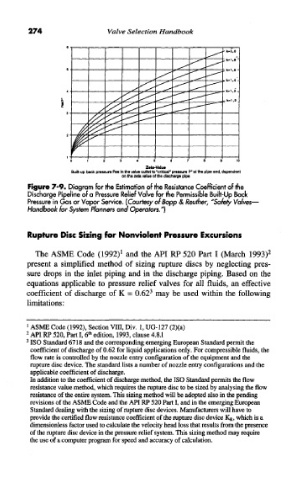
Figure 7-9. Diagram for the Estimation of the Resistance Coefficient of the
Discharge Pipeline of a Pressure Relief Valve for the Permissible Built-Up Back
Pressure in Gas or Vapor Service. (Courtesy ofBopp & Reuther, "Safety Valves-
Handbook for System Planners and Operators."]
Rupture Disc Sizing for Nonviolent Pressure Excursions
The ASME Code (1992) 1 and the API RP 520 Part I (March 1993) 2
present a simplified method of sizing rupture discs by neglecting pres-
sure drops in the inlet piping and in the discharge piping. Based on the
equations applicable to pressure relief valves for all fluids, an effective
coefficient of discharge of K = 0.62 3 may be used within the following
limitations:
1
ASME Code (1992), Section VIII, Div. 1, UG-127 (2)(a)
2 th
API RP 520, Part I, 6 edition, 1993, clause 4.8.1
3
ISO Standard 6718 and the corresponding emerging European Standard permit the
coefficient of discharge of 0.62 for liquid applications only. For compressible fluids, the
flow rate is controlled by the nozzle entry configuration of the equipment and the
rupture disc device. The standard lists a number of nozzle entry configurations and the
applicable coefficient of discharge.
In addition to the coefficient of discharge method, the ISO Standard permits the flow
resistance value method, which requires the rupture disc to be sized by analysing the flow
resistance of the entire system. This sizing method will be adopted also in the pending
revisions of the ASME Code and the API RP 520 Part I, and in the emerging European
Standard dealing with the sizing of rupture disc devices. Manufacturers will have to
provide the certified flow resistance coefficient of the rupture disc device K R, which is a
dimensionless factor used to calculate the velocity head loss that results from the presence
of the rupture disc device in the pressure relief system. This sizing method may require
the use of a computer program for speed and accuracy of calculation.