
Page 36 - Valve Selection Handbook
P. 36
Fundamentals 23
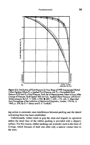
Figure 2-3. Distribution Aof Fluid Pressure for Four Rings of PTFE-lmpregnated Plaited
Cotton Pqcking Where Pf = Applied Fluid Pressure and Pf = Normalized Fluid
Pressure Pf/Pf and Pf = Fluid Pressure. Each Set of Measurements Taken 6 Hours After
2
Change or Pressure. Shaft Speed: 850 rev/min. Applied Gland Pressure: 250 Ib/in .
2
Water pressure, Ib/in : O 1000, A 700, • 400, D 250, x 75, +26, 2. (Reprinted
from Proceedings of the Institution of Mechanical Engineers, London, 174 No. 6,
I960, p. 278, by D. F. Denny and D. E. Turnbull.)
ing action is automatic once interference between packing and the lateral
restraining faces has been established.
Unfortunately, rubber tends to grip the stem and impede its operation
unless the inner face of the rubber packing is provided with a slippery
surface. For this reason, rubber packings are normally used in the form of
O-rings, which because of their size offer only a narrow contact face to
the stem.