
Page 41 - Valve Selection Handbook
P. 41
28 Valve Selection Handbook
where
p = density of fluid
g = local acceleration due to gravity
The equations are valid for single-phase flow of Newtonian liquids
and for both turbulent and laminar flow conditions. They may also be
used for flow of gas at low Mach numbers. As the Mach number at the
valve inlet approaches 0.2, the effects of compressibility become notice-
17
able but are unlikely to be significant even for Mach numbers up to 0.5.
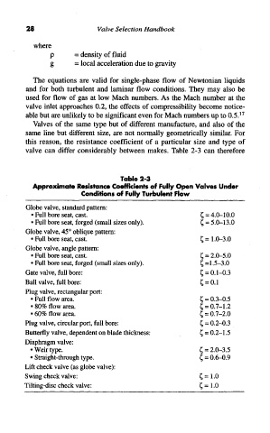
Valves of the same type but of different manufacture, and also of the
same line but different size, are not normally geometrically similar. For
this reason, the resistance coefficient of a particular size and type of
valve can differ considerably between makes. Table 2-3 can therefore
Table 2-3
Approximate Resistance Coefficients of Fully Open Valves Under
Conditions of Fully Turbulent Flow
Globe valve, standard pattern:
• Full bore seat, cast. £ = 4.0-10.0
• Full bore seat, forged (small sizes only). £ = 5.0-13.0
Globe valve, 45° oblique pattern:
• Full bore seat, cast. £ = 1.0-3.0
Globe valve, angle pattern:
• Full bore seat, cast. £ = 2.0-5.0
• Full bore seat, forged (small sizes only). £ =1.5-3.0
Gate valve, full bore: £ = 0.1-0.3
Ball valve, full bore: £ = 0.1
Plug valve, rectangular port:
• Full flow area. £ = 0.3-0.5
• 80% flow area. £ = 0.7-1.2
• 60% flow area. £ = 0.7-2.0
Plug valve, circular port, full bore: £ = 0.2-0.3
Butterfly valve, dependent on blade thickness: £ = 0.2-1.5
Diaphragm valve:
• Weir type. £ = 2.0-3.5
• Straight-through type. £ = 0.6-0.9
Lift check valve (as globe valve):
Swing check valve: £ = 1.0
Tilting-disc check valve: £ = 1.0