
Page 65 - Valve Selection Handbook
P. 65
52 Valve Selection Handbook
lar duty at the lowest cost. The valves shown in Figure 3-2 through Fig-
ure 3-11 are representative of the many variations that are commonly
used in pipelines for the control of flow. Those shown in Figure 3-12
through Figure 3-14 are specialty valves, which are designed to meet a
special duty, as described in the captions of these illustrations.
An inspection of these illustrations shows numerous variations in
design detail. These are discussed in the following section.
Valve Body Patterns
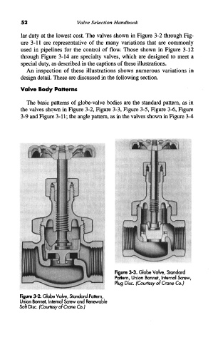
The basic patterns of globe-valve bodies are the standard pattern, as in
the valves shown in Figure 3-2, Figure 3-3, Figure 3-5, Figure 3-6, Figure
3-9 and Figure 3-11; the angle pattern, as in the valves shown in Figure 3-4
Figure 3-3. Globe Valve, Standard
Pattern, Union Bonnet, Internal Screw,
Plug Disc. (Courtesy of Crane Co.)
Figure 3-2. Globe Valve, Standard Pattern,
Union Bonnet, Internal Screw and Renewable
Soft Disc. (Courtesy of Crane Co.)