
Page 88 - Valve Selection Handbook
P. 88
Manual Valves 75
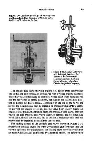
Figure 3-30. Conduit Gate Valve with Floating Seats
and Expandable Disc. (Courtesy of W.K.M. Valve
Division, ACF Industries, Inc.) -»
Figure 3-31. Conduit Gate Valve
with Automatic Injection of a
Sealant to the Downstream
Seatings Each Time the Valve
Closes. (Courtesy of McEvoy
Oilfield Equipment Company.)
The conduit gate valve shown in Figure 3-30 differs from the previous
one in that the disc consists of two halves with a wedge-shaped interface.
These halves are interlinked so that they wedge apart when being moved
into the fully open or closed positions, but relax in the intermediate posi-
tion to permit the disc to travel. Depending on the use of the valve, the
face of the floating seats may be metallic or provided with a PTFE insert.
To prevent the ingress of solids into the valve body cavity during all
stages of disc travel, the floating seats are provided with skirts, between
which the disc travels. This valve likewise permits double block and
bleed. Also, should the seat seal fail in service, a temporary seat seal can
be provided by injecting a sealant into the seat face.
The sealing action of the conduit gate valve shown in Figure 3-31
depends on a sealant that is fed to the downstream seat face each time the
valve is operated. For this purpose, the floating seats carry reservoirs that
are filled with a sealant and topped by a floating piston. The entire valve