
Page 86 - Valve Selection Handbook
P. 86
Manual Valves 73
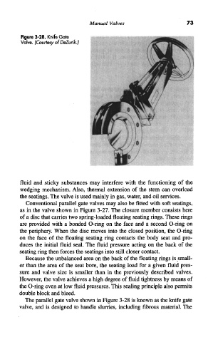
Figure 3-28. Knife Gate
Valve. (Courtesy of DeZurik.)
fluid and sticky substances may interfere with the functioning of the
wedging mechanism. Also, thermal extension of the stem can overload
the seatings. The valve is used mainly in gas, water, and oil services.
Conventional parallel gate valves may also be fitted with soft seatings,
as in the valve shown in Figure 3-27. The closure member consists here
of a disc that carries two spring-loaded floating seating rings. These rings
are provided with a bonded O-ring on the face and a second O-ring on
the periphery. When the disc moves into the closed position, the O-ring
on the face of the floating seating ring contacts the body seat and pro-
duces the initial fluid seal. The fluid pressure acting on the back of the
seating ring then forces the seatings into still closer contact.
Because the unbalanced area on the back of the floating rings is small-
er than the area of the seat bore, the seating load for a given fluid pres-
sure and valve size is smaller than in the previously described valves.
However, the valve achieves a high degree of fluid tightness by means of
the O-ring even at low fluid pressures. This sealing principle also permits
double block and bleed.
The parallel gate valve shown in Figure 3-28 is known as the knife gate
valve, and is designed to handle slurries, including fibrous material. The