
Page 232 - Video Coding for Mobile Communications Efficiency, Complexity, and Resilience
P. 232
Section 9.5. Error Detection 209
(a) Spatial error propagation in the third frame (b) Temporal error propagation in the sixth
frame
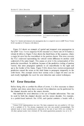
Figure 9.2: Spatial and temporal error propagation due to a single-bit error in QSIF TABLE TENNIS
H.263 encoded at 10 frames=s (46 kbits=s)
Figure 9.2 shows an example of spatial and temporal error propagation in
1
the QSIF TABLE TENNIS sequence H.263 encoded at a frame rate of 10 frames=s
(about 46 kbits=s). Figure 9.2(a) shows the third frame of the sequence, where
a single bit error hits the macroblock in the position shown. This error converts
the VLC codeword representing the vertical vector di erence to another valid
codeword of the same length. This causes an error in the compensation of this
particular macroblock. In addition, because of the predictive coding of motion
vectors, this error propagates spatially to all macroblocks to the right and
up to the border of the frame. Figure 9.2(b) shows how motion-compensated
prediction caused the errors in the third frame to propagate temporally to the
sixth frame. This example shows how serious even a single bit error can be
and clearly highlights the need for error detection and control techniques.
9.5 Error Detection
Before being able to combat the e ects of errors, it is rst necessary to detect
whether and where errors have occurred. Error detection can be performed by
the channel decoder and=or the source decoder.
One method for error detection is the use of header information. This can
be used by both the channel decoder and the source decoder. For example,
in a packet-based network like ATM, each packet contains a header with a
1 Telenor H.263 implementation was used. The luma component was zero padded to 128 lines
to be a multiple of 16. The chroma components were also zero padded correspondingly. The
optional mode to insert synchronization codewords at the start of each GOB was switched on.
All other optional modes were switched o . The initial quantization parameter was set to 10.