
Page 206 - Materials Chemistry, Second Edition
P. 206
CAT3525_C07.qxd 1/29/2005 9:57 AM Page 177
Municipal Solid Waste Processing; Materials Recovery Facilities 177
Horizontal and inclined belt conveyors, where the material is carried along the surface of the
belt, and drag conveyors, equipped with crossbars to drag the input wastes, are the most commonly
used conveyors for handling MSW (Figure 7.5) (Tchobanoglous et al., 1993).
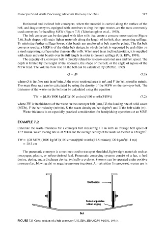
The belt conveyor can be designed with idler rolls that create a concave cross-section (Figure
7.6). Such shapes will retain lighter materials along the length of the belt, thus preventing spillage.
To minimize further spillage losses, skirt bands are employed at belt transfer points. The flat belt
conveyor used at a MRF is of the slider belt design, in which the belt is supported by and slides on
a steel supporting surface rather than on idler rolls. When used in an inclined position, it is supplied
with cleats and skirt boards over its full length in order to prevent spillage (U.S. EPA, 1991).
The capacity of a conveyor belt is directly related to its cross-sectional area and belt speed. The
depth is limited by the height of the sidewalls, the shape of the belt, or the angle of repose of the
MSW feed. The volume flow rate on the belt can be calculated by (Pfeffer, 1992)
Q AV (7.1)
3
2
where Q is the flow rate in m /min, A the cross-sectional area in m , and V the belt speed in m/min.
The mass flow rate can be calculated by using the density of the MSW on the conveyor belt. The
thickness of the waste on the belt can be calculated using the equation
TW [(LR)(1000 kg/MT)(100 cm/m)]/[(60 min/h)(VDW)] (7.2)
where TW is the thickness of the waste on the conveyor belt (cm), LR the loading rate of solid waste
3
(MT/h), V the belt velocity (m/min), D the waste density on belt (kg/m ) and W the belt width (m).
Waste thickness is an especially practical consideration for handpicking operations at an MRF.
EXAMPLE 7.2
Calculate the waste thickness for a conveyor belt measuring 1.1 m with an average belt speed of
3
17.5 m/min. Waste loading rate is 28 MT/h and the average density of the waste on the belt is 120 kg/m .
3
TW [(28 MT/h)(1000 kg/MT)(100 cm/m)]/[(60 min/h)(17.5 m/min)(120 kg/m )(1.1 m)]
20.2 cm
The pneumatic conveyor is sometimes used to transport shredded, lightweight materials such as
newspaper, plastic, or refuse-derived fuel. Pneumatic conveying systems consist of a fan, a feed
device, piping, and a discharge device, typically a cyclone. Systems can be operated under positive
pressure (i.e., blowing air) or negative pressure (suction). Air velocities for processed wastes are in
FIGURE 7.5 Cross-section of a belt conveyor (U.S. EPA, EPA/625/6-91/031, 1991).