
Page 202 - Materials Chemistry, Second Edition
P. 202
CAT3525_C07.qxd 1/29/2005 9:57 AM Page 173
Municipal Solid Waste Processing; Materials Recovery Facilities 173
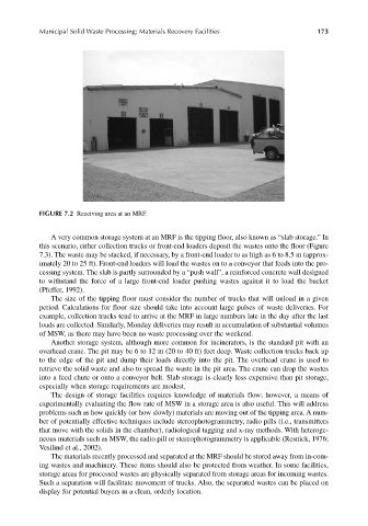
FIGURE 7.2 Receiving area at an MRF.
A very common storage system at an MRF is the tipping floor, also known as “slab storage.” In
this scenario, either collection trucks or front-end loaders deposit the wastes onto the floor (Figure
7.3). The waste may be stacked, if necessary, by a front-end loader to as high as 6 to 8.5 m (approx-
imately 20 to 25 ft). Front-end loaders will load the wastes on to a conveyor that feeds into the pro-
cessing system. The slab is partly surrounded by a “push wall”, a reinforced concrete wall designed
to withstand the force of a large front-end loader pushing wastes against it to load the bucket
(Pfeffer, 1992).
The size of the tipping floor must consider the number of trucks that will unload in a given
period. Calculations for floor size should take into account large pulses of waste deliveries. For
example, collection trucks tend to arrive at the MRF in large numbers late in the day after the last
loads are collected. Similarly, Monday deliveries may result in accumulation of substantial volumes
of MSW, as there may have been no waste processing over the weekend.
Another storage system, although more common for incinerators, is the standard pit with an
overhead crane. The pit may be 6 to 12 m (20 to 40 ft) feet deep. Waste collection trucks back up
to the edge of the pit and dump their loads directly into the pit. The overhead crane is used to
retrieve the solid waste and also to spread the waste in the pit area. The crane can drop the wastes
into a feed chute or onto a conveyor belt. Slab storage is clearly less expensive than pit storage,
especially when storage requirements are modest.
The design of storage facilities requires knowledge of materials flow; however, a means of
experimentally evaluating the flow rate of MSW in a storage area is also useful. This will address
problems such as how quickly (or how slowly) materials are moving out of the tipping area. A num-
ber of potentially effective techniques include stereophotogrammetry, radio pills (i.e., transmitters
that move with the solids in the chamber), radiological tagging and x-ray methods. With heteroge-
neous materials such as MSW, the radio pill or stereophotogrammetry is applicable (Resnick, 1976;
Vesilind et al., 2002).
The materials recently processed and separated at the MRF should be stored away from in-com-
ing wastes and machinery. These items should also be protected from weather. In some facilities,
storage areas for processed wastes are physically separated from storage areas for incoming wastes.
Such a separation will facilitate movement of trucks. Also, the separated wastes can be placed on
display for potential buyers in a clean, orderly location.