
Page 280 - Materials Chemistry, Second Edition
P. 280
CAT3525_C09.qxd 2/8/2005 10:11 AM Page 251
Incineration of MSW 251
Combustion
chamber
Flue
Crane
(stack)
Boiler
Charging
Tipping chute
area
Air
Traveling
Storage Ash recovery pollution
grates
area control
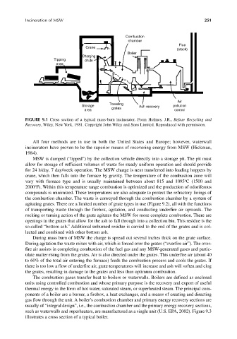
FIGURE 9.1 Cross section of a typical mass-burn incinerator. From Holmes, J.R., Refuse Recycling and
Recovery, Wiley, New York, 1981. Copyright John Wiley and Sons Limited. Reproduced with permission.
All four methods are in use in both the United States and Europe; however, waterwall
incinerators have proven to be the superior means of recovering energy from MSW (Hickman,
1984).
MSW is dumped (“tipped”) by the collection vehicle directly into a storage pit. The pit must
allow for storage of sufficient volumes of waste for steady uniform operation and should provide
for 24 h/day, 7 day/week operation. The MSW charge is next transferred into loading hoppers by
crane, which then falls into the furnace by gravity. The temperature of the combustion zone will
o
vary with furnace type and is usually maintained between about 815 and 1095 C (1500 and
o
2000 F). Within this temperature range combustion is optimized and the production of odoriferous
compounds is minimized. These temperatures are also adequate to protect the refractory linings of
the combustion chamber. The waste is conveyed through the combustion chamber by a system of
agitating grates. There are a limited number of grate types in use (Figure 9.2), all with the functions
of transporting waste through the firebox, agitation, and conducting underfire air upwards. The
rocking or turning action of the grate agitates the MSW for more complete combustion. There are
openings in the grates that allow for the ash to fall through into a collection bin. This residue is the
so-called “bottom ash.” Additional unburned residue is carried to the end of the grates and is col-
lected and combined with other bottom ash.
During mass burn of MSW the charge is spread out several inches thick on the grate surface.
During agitation the waste mixes with air, which is forced over the grates (“overfire air”). The over-
fire air assists in completing combustion of the fuel gas and any MSW-generated gases and partic-
ulate matter rising from the grates. Air is also directed under the grates. This underfire air (about 40
to 60% of the total air entering the furnace) feeds the combustion process and cools the grates. If
there is too low a flow of underfire air, grate temperatures will increase and ash will soften and clog
the grates, resulting in damage to the grates and less than optimum combustion.
The combustion gases transfer heat to boilers or waterwalls. Boilers are defined as enclosed
units using controlled combustion and whose primary purpose is the recovery and export of useful
thermal energy in the form of hot water, saturated steam, or superheated steam. The principal com-
ponents of a boiler are a burner, a firebox, a heat exchanger, and a means of creating and directing
gas flow through the unit. A boiler’s combustion chamber and primary energy recovery sections are
usually of “integral design”, i.e., the combustion chamber and the primary energy recovery sections,
such as waterwalls and superheaters, are manufactured as a single unit (U.S. EPA, 2002). Figure 9.3
illustrates a cross section of a typical boiler.