
Page 516 - Materials Chemistry, Second Edition
P. 516
CAT3525_C15.qxd 1/27/2005 12:40 PM Page 487
Incineration of Hazardous Wastes 487
combustion chamber. The major subsystems that may occur in a hazardous waste incinerator are
(Oppelt, 1987):
● Waste preparation and feeding
● Combustion chamber(s)
● Air pollution control
● Ash handling and disposal
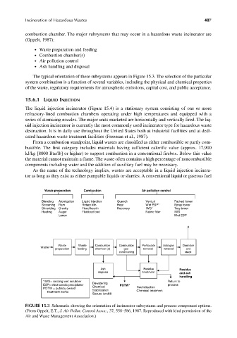
The typical orientation of these subsystems appears in Figure 15.3. The selection of the particular
system combination is a function of several variables, including the physical and chemical properties
of the waste, regulatory requirements for atmospheric emissions, capital cost, and public acceptance.
15.6.1 LIQUID INJECTION
The liquid injection incinerator (Figure 15.4) is a stationary system consisting of one or more
refractory-lined combustion chambers operating under high temperatures and equipped with a
series of atomizing nozzles. The major units marketed are horizontally and vertically fired. The liq-
uid injection incinerator is currently the most commonly used incinerator type for hazardous waste
destruction. It is in daily use throughout the United States both at industrial facilities and at dedi-
cated hazardous waste treatment facilities (Freeman et al., 1987).
From a combustion standpoint, liquid wastes are classified as either combustible or partly com-
bustible. The first category includes materials having sufficient calorific value (approx. 17,900
kJ/kg [8000 Btu/lb] or higher) to support combustion in a conventional firebox. Below this value
the material cannot maintain a flame. The waste often contains a high percentage of noncombustible
components including water and the addition of auxiliary fuel may be necessary.
As the name of the technology implies, wastes are acceptable in a liquid injection incinera-
tor as long as they exist as either pumpable liquids or slurries. A conventional liquid or gaseous fuel
Waste preparation Combustion Air pollution control
Blending Atomization Liquid injection Quench Venturi Packed tower
Screening Ram Rotary kiln Heat Wet ESP* Spray tower
Shredding Gravity Fixed hearth Recovery IWS* Tray tower
Heating Auger Fluidized bed Fabric filter IWS
Lance Wet ESP
Waste Waste Combustion Combustion Particulate Acid gas Demister
Waste
preparation feeding chamber (s) gas removal removal and
conditioning stack
Ash Residue Residue
disposal treatment and ash
handling
*IWS= ionizing wet scrubber Return to
ESP= electrostatic precipitator Dewatering POTW* process
Chemical
POTW = publicly owned Neutralization
treatment works Stabilization Chemical treatment
Secure landfill
FIGURE 15.3 Schematic showing the orientation of incinerator subsystems and process component options.
(From Oppelt, E.T., J. Air Pollut. Control Assoc., 37, 558–586, 1987. Reproduced with kind permission of the
Air and Waste Management Association.)