
Page 518 - Materials Chemistry, Second Edition
P. 518
CAT3525_C15.qxd 1/27/2005 12:40 PM Page 489
Incineration of Hazardous Wastes 489
Diffuser
Atomizer
Fuel supply Atomizer tip
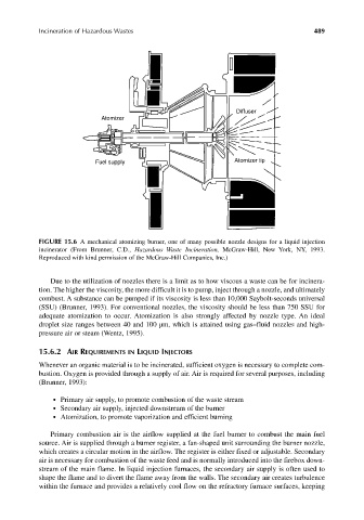
FIGURE 15.6 A mechanical atomizing burner, one of many possible nozzle designs for a liquid injection
incinerator (From Brunner, C.D., Hazardous Waste Incineration, McGraw-Hill, New York, NY, 1993.
Reproduced with kind permission of the McGraw-Hill Companies, Inc.)
Due to the utilization of nozzles there is a limit as to how viscous a waste can be for incinera-
tion. The higher the viscosity, the more difficult it is to pump, inject through a nozzle, and ultimately
combust. A substance can be pumped if its viscosity is less than 10,000 Saybolt-seconds universal
(SSU) (Brunner, 1993). For conventional nozzles, the viscosity should be less than 750 SSU for
adequate atomization to occur. Atomization is also strongly affected by nozzle type. An ideal
droplet size ranges between 40 and 100 µm, which is attained using gas–fluid nozzles and high-
pressure air or steam (Wentz, 1995).
15.6.2 AIR REQUIREMENTS IN LIQUID INJECTORS
Whenever an organic material is to be incinerated, sufficient oxygen is necessary to complete com-
bustion. Oxygen is provided through a supply of air. Air is required for several purposes, including
(Brunner, 1993):
● Primary air supply, to promote combustion of the waste stream
● Secondary air supply, injected downstream of the burner
● Atomization, to promote vaporization and efficient burning
Primary combustion air is the airflow supplied at the fuel burner to combust the main fuel
source. Air is supplied through a burner register, a fan-shaped unit surrounding the burner nozzle,
which creates a circular motion in the airflow. The register is either fixed or adjustable. Secondary
air is necessary for combustion of the waste feed and is normally introduced into the firebox down-
stream of the main flame. In liquid injection furnaces, the secondary air supply is often used to
shape the flame and to divert the flame away from the walls. The secondary air creates turbulence
within the furnace and provides a relatively cool flow on the refractory furnace surfaces, keeping