
Page 517 - Materials Chemistry, Second Edition
P. 517
CAT3525_C15.qxd 1/27/2005 12:40 PM Page 488
488 Waste Management Practices: Municipal, Hazardous, and Industrial
2600−3000°F
Discharge
Excess
air
Liquid waste
Atomized vapor
Fuel
Liquid waste Flame
Air
Refractory
liner
FIGURE 15.4 A liquid injection incinerator. (From Oppelt, E.T., J. Air Pollut. Control Assoc., 37, 558–586,
1987. Reproduced with kind permission of the Air and Waste Management Association.)
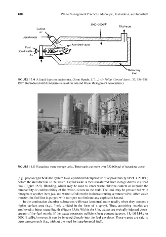
FIGURE 15.5 Hazardous waste storage tanks. These tanks can store over 350,000 gal of hazardous waste.
(e.g., propane) preheats the system to an equilibrium temperature of approximately 815°C (1500°F)
before the introduction of the waste. Liquid waste is then transferred from storage drums to a feed
tank (Figure 15.5). Blending, which may be used to lower waste chlorine content or improve the
pumpability or combustibility of the waste, occurs in the tank. The tank may be pressurized with
nitrogen or another inert gas, and waste is fed into the incinerator using a remote valve. After waste
transfer, the fuel line is purged with nitrogen to eliminate any explosion hazard.
In the combustion chamber substances will react (combust) more readily when they possess a
higher surface area (e.g., finely divided in the form of a spray). Thus, atomizing nozzles are
employed to inject waste liquids (Figure 15.6). Within the kiln, wastes are typically injected down-
stream of the fuel nozzle. If the waste possesses sufficient heat content (approx. 13,400 kJ/kg or
6000 Btu/lb), however, it can be injected directly into the fuel envelope. These wastes are said to
burn autogenously (i.e., without the need for supplemental fuel).